
FM
Reception and Multipath
How Summit Public Radio's Signals Reach Our Listeners
By John Roberts
If your Summit County home is in one of those rare locations from which the Baldy Mountain electronics site (where all of our transmitters are) is visible, you can receive our FM transmissions by direct "line-of-sight" path and will have a strong clear signal. Since we live in a very mountainous community, many of our homes are not so ideally located. FM radio waves can arrive by a variety of methods. The best after direct line-of-sight is what might be called "almost-line-of-sight" wherein the FM signal is bent slightly by ground, hills, ridges, etc. (An imperfect analogy is seeing the glow of the setting sun just after it has dropped below the horizon.) This can also provide a strong clear signal and applies to many of our homes. A third path that the FM signal may take is to reflect off a large distant object such as a mountain or a close smaller object like a semi-trailer or an airplane passing overhead.
Unfortunately, at any location in the County, the signal can arrive at our homes by all these methods at once. When this happens, the signals combine at the receiver antenna and the result is a "multipath" signal. One might think this is good and will result in a stronger signal. Unfortunately this is probably not going to be the case. The wavelength of our FM signals is about nine feet. If the path length of one signal is nine feet or any integer multiple of nine feet different from another they will combine "in phase" and produce a stronger signal. (This is the "constructive wave interference that you might recall from high- school science.) However, if the path length is 4.5 feet, or any length of 4.5 feet plus an integer multiple of nine feet the two signals will be "180 degrees out of phase" and one signal will wholly or partially cancel the other. (This is "destructive wave interference" or in radio engineer's jargon, "phase cancellation.")
This helps to explain some of the things we observe about our FM reception. You may have noticed that if we move our FM antenna to a different position, we may get better or worse reception. In this case, we are changing the path lengths of the multiple paths. Since 4.5 feet can make all the difference, the space in our living rooms is big enough to significantly alter the combined multipath signal. So as we move a few feet around the room, the signal can be reinforced or partly canceled. (Repositioning your antenna is the first thing to try when attempting to improve FM reception.) Any movement that changes the relative path length of two incoming radio waves will effect the signal strength at your antenna. Consider a moving car radio or a portable radio such as a Walkman. If multipath reception is involved, as the receiver moves the relative path lengths are constantly changing. This results in the momentary fading that we sometimes hear, a nulling effect which has been likened to moving around on a slice of Swiss cheese. This same effect is routinely created by an airplane flying overhead. In this case it is the movement of the reflecting object that causes the relative path length to change causing the net signal at your antenna to vary. This helps to explain one cause of the variations of signal strength sometimes experienced here in Summit County. The next section addresses in greater depth how to overcome the effects of multipath propagation.
Tips for Improving FM Receiver Performance
Sometimes just moving a radio to a different location in a room will improve reception. Desktop and portable radios often have telescoping antennas or use the power cord or headphone cord as the antenna. When using one of these receivers, the position of the unit and the orientation of the antenna can be critical. If your receiver uses its power cord as an antenna, stretching out or moving the cord can improve reception. An inexpensive T-shaped, flexible wire antenna called an FM dipole antenna can be added to radios that have rear terminals labeled “antenna.” After you have added the dipole antenna to a radio, the antenna should be turned for the best reception. These antennas are designed to be mounted flat against a wall or strung diagonally between two adjacent walls. If the dipole offers no appreciable improvement, you may need a directional external antenna. Designed specifically for FM reception, these look like TV antennas and are usually installed on a roof, on the sides of buildings or in an attic, with a piece of Cablevision wire (that's 75 ohm coaxial cable) running down to your radio. Again, after connecting the antenna to your receiver, reorient it until you get the best reception.
|
|
|
Try the following one at a time and see if there is an improvement:
1) Adjust the chassis-mounted receive antenna.
2) Replace the chassis-mounted receive antenna with an "external" receive antenna fastened to the wall behind the receiver.
3) Rotate the external receive antenna and also try turning it to a vertical orientation.
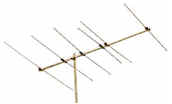
4) Install a high-gain directional outdoor antenna:
a) to suppress multipath reception;
b) to provide a better signal to noise ratio.A) Do-it-yourself: TV Antenna Installation Guide and The Antenna Primer
1) Mechanical considerations: mounting hardware; masts
2) Antennas: dipole; beam (high-gain directional Yagi); amplified antennas; antenna polarization.
3) Transmission lines and impedance matching: 300 ohm twinlead; 75 ohm coaxial cable (RG-59, RG-6 & "F" connectors); 300 ohm to 75 ohm matching transformers.
B) Professional antenna installation.
C) Publications
1) Antennas -- Selection, Installation and Projects, Alvis J. Evans
D) Radio-Frequency Engineering Tutorials
1) Antenna Patterns and Polarizations -- antenna "azimuth" and "elevation" patterns, and "horizontal" and "vertical" patterns
3) Field Intensity Units -- dBu, dBm, dBuV, and other units; the gain of a dipole referenced to an ideal isotropic radiator is 2.15 dB.
4) Directive Short Wave Antenna, 1924 -- the Yagi-Uda antenna system
5) Software Defined FM Radio -- How to receive and demodulate off-the-air FM radio signals with a digital computer.
6) Digital Television Guide -- The Layperson's Guide to Digital TV